
|
Description
|
|
The LiIon component models a lithium-ion battery using order-reduced equations derived from John Newman’s works on porous-electrode theory [1-3]. The following figure shows the basic anatomy of a lithium-ion cell, which has four main components: the negative composite electrode connected to the negative terminal of the cell, the positive electrode connected to the positive terminal of the cell, the separator, and the electrolyte. The chemistries of the positive and negative electrodes are independently selectable and define the electrochemical and thermal behaviors of the battery.
Main chemical reactions (assuming cathode and anode).
Cathode:
Anode:
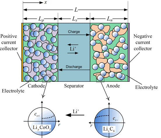
During battery operation, the position lithium ions () travel between the two electrodes via diffusion and ionic conduction through the porous separator and the surface of the active material particles where they undergo electrochemical reactions. This process is called intercalation.
|
|
Electrochemical Behavior
|
|
|
|
Transport in solid phase
|
|
The following partial differential equation (PDE) describes the solid phase concentration in a single spherical active material particle in solid phase:
where is the diffusion coefficient in the intercalation particle of the electrodes.
|
|
|
Transport in electrolyte
|
|
The concentration in the electrolyte phase changes due to the changes in the gradient diffusive flow of ions and is described by the following PDE:
where
|
|
is the diffusion coefficient in the electrolyte,
|
|
|
is the specific surface area of electrode,
|
|
|
is the radius of intercalation of electrode
|
|
|
is the volume fraction of fillers
|
|
|
is the transference constant in the electrolyte, and
|
|
|
is the wall-flux of on the intercalation particle of electrode.
|
|
|
|
Electrical potentials
|
|
Charge conservation in the solid phase of each electrode is described by Ohm’s law:
In the electrolyte phase, the electrical potential is described by combining Kirchhoff’s law and Ohm’s law:
where
|
|
is the effective electronic conductivity,
|
|
|
is the electronic conductivity in solid phase,
|
|
|
is the effective ionic conductivity of the electrolyte, and
|
|
|
is the applied current density.
|
|
|
|
Butler-Volmer kinetics
|
|
The Butler-Volmer equation describes the relationship between the current density, concentrations, and over-potential:
where
|
|
is the reaction rate constant,
|
|
|
is the over-potential of the intercalation reaction,
|
|
|
is maximum concentration of ions in the intercalation particles of the electrode,
|
|
|
is the concentration of of ions on the surface of the intercalation particles of the electrode, and
|
|
|
is the open-circuit potential for the electrode material.
|
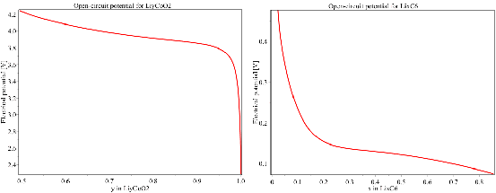
The open-circuit potential for each cathode and anode material has been curve-fitted based on experimental measurements.
An example of the open-circuit potentials for cathode and anode, curve-fitted from experiment measurement, are shown in the following figure:
|
|
|
|
Degradation
|
|
The gradual decay, with use, of a cell's capacity and increase of its resistance is modeled by enabling the include degradation effects boolean parameter. Enabling this feature adds a state-of-health (soh) output to the model. This signal is 1 when the cell has no decay and 0 when is completely decayed.
The soh output is given by
where
|
|
is thickness of the solid-electrolyte interface (SEI),
|
|
|
is radius of the particles of active material in the SEI.
|
The decay of the capacity is
where
|
|
is the effective capacity, and
|
|
|
is the specified capacity equal to either the parameter or the input .
|
The additional series resistance added to a cell is
with a parameter of the model.
The following equations govern the increase in the thickness of the SEI layer ().
|
|
|
Thermal Effects
|
|
Select the thermal model of the battery from the heat model drop-down list. The available models are: isothermal, external port, and convection.
|
|
Isothermal
|
|
The isothermal model sets the cell temperature to a constant parameter, .
|
|
|
External Port
|
|
The external port model adds a thermal port to the battery model. The temperature of the heat port is the cell temperature. The parameters and become available and are used in the heat equation
where is the heat generated in each cell, including chemical reactions and ohmic resistive losses, is the heat flow out of each cell, and is the heat flow out of the external port.
|
|
|
Convection
|
|
The convection model assumes the heat dissipation from each cell is due to uniform convection from the surface to an ambient temperature. The parameters , , , , and become available, as does an output signal port that gives the cell temperature in Kelvin. The heat equation is the same as the heat equation for the external port, with given by
|
|
|
Arrhenius equations
|
|
For all thermal models, the Arrhenius equations model the effect of cell temperature on the chemical reaction.
with .
|
|
|
|
State of Charge
|
|
A signal output, soc, gives the state-of-charge of the battery, with 0 being fully discharged and 1 being fully charged.
The parameter sets the minimum allowable state-of-charge; if the battery is discharged past this level, the simulation is terminated and an error message is raised. This prevents the battery model from reaching non-physical conditions. A similar effect occurs if the battery is fully charged so that the state of charge reaches one.
The parameter assigns the initial state-of charge of the battery.
|
|
|
Capacity
|
|
The capacity of a cell can either be a fixed value, , or be controlled via an input signal, , if the use capacity input box is checked.
|
|
|
Resistance
|
|
The resistance of each cell can either be a fixed value, , or be controlled via an input signal, , if the use cell resistance input box is checked.
|
|
|
|
Variables
|
|
|
Name
|
Units
|
Description
|
Modelica ID
|
|
|
|
Internal temperature of battery
|
Tcell
|
|
|
|
Current into battery
|
i
|
|
|
|
Voltage across battery
|
v
|
|
|
|
|
|
Connections
|
|
|
Name
|
Type
|
Description
|
Modelica ID
|
|
|
Electrical
|
Positive pin
|
p
|
|
|
Electrical
|
Negative pin
|
n
|
|
|
Real output
|
State of health [0..1]; available when include degradation effects is enabled
|
soh
|
|
|
Real output
|
State of charge [0..1]
|
SOC
|
|
|
Real input
|
Sets capacity of cell, in ampere hours; available when use capacity input is true
|
Cin
|
|
|
Real input
|
Sets resistance of cell, in Ohms; available when use resistance input is true
|
Rin
|
|
|
Real output
|
Temperature of cell, in Kelvin; available with convection heat model
|
Tout
|
|
|
Thermal
|
Thermal connection; available with external port heat model
|
heatPort
|
|
|
|
|
|
Electrode Chemistry Parameters
|
|
|
Name
|
Default
|
Units
|
Description
|
Modelica ID
|
|
|
LiCoO2
|
|
Chemistry of the positive electrode
|
chem_pos
|
|
|
Graphite
|
|
Chemistry of the negative electrode
|
chem_neg
|
|
|
The chem_pos and chem_neg parameters select the chemistry of the positive and negative electrodes, respectively. They are of types MaplesoftBattery.Selector.Chemistry.Positive and MaplesoftBattery.Selector.Chemistry.Negative. The selection affects the variation in the open-circuit electrode potential and the chemical reaction rate versus the concentration of lithium ions in the intercalation particles of the electrode.
If the Use input option is selected for either the positive or negative electrode, a vector input port appears next to the corresponding electrode. The port takes two real signals, and , where specifies the potential in volts at the electrode and specifies the entropy in .
If any of the chem_pos materials , , , , or is selected, the isothermal model is used.
If the Use interpolation table option is selected for either the positive or negative electrode, a 2-D table defines the electrode potential and entropy in terms of the state-of-charge. The mode option selects whether the table is defined by an attachment, a file, or inline. The table has three columns:
The first column is the state-of-charge (soc), a real number between 0 and 1.
The second column is the electrode potential () in volts.
The third column is the electrode entropy () in .
Supported positive electrode materials
|
Chemical composition
|
Chemical name
|
Common name
|
|
|
Lithium Cobalt Oxide
|
LCO
|
|
|
Lithium Iron Phosphate
|
LFP
|
|
|
Lithium Manganese Oxide
|
LMO
|
|
- low plateau
|
Lithium Manganese Oxide
|
|
|
|
Lithium Manganese Oxide
|
|
|
|
Lithium Nickel Cobalt Aluminum Oxide
|
NCA
|
|
|
Lithium Nickel Cobalt Oxide
|
|
|
|
Lithium Nickel Cobalt Oxide
|
|
|
|
Lithium Nickel Manganese Cobalt Oxide
|
NMC
|
|
|
Lithium Nickel Oxide
|
|
|
|
Lithium Titanium Sulphide
|
|
|
|
Lithium Vanadium Oxide
|
|
|
|
Lithium Tungsten Oxide
|
|
|
|
Sodium Cobalt Oxide
|
|
|
|
Supported negative electrode materials
|
Chemical composition
|
Chemical name
|
Common name
|
|
|
Lithium Carbide
|
Graphite
|
|
|
Lithium Titanium Oxide
|
|
|
|
Lithium Titanate
|
LTO
|
|
|
|
|
|
Degradation Parameters
|
|
|
Name
|
Default
|
Units
|
Description
|
Modelica ID
|
|
|
1.2
|
|
Factor for reaction rate equation
|
Ae
|
|
|
|
|
Diffusion coefficient at standard conditions
|
D0
|
|
|
10000
|
|
Activation energy
|
Ea
|
|
|
0.026
|
|
Molar mass of SEI layer
|
M
|
|
|
|
|
Radius of particles of active material in anode
|
Rs
|
|
|
1
|
|
Initial state-of-health:
|
SoH0
|
|
|
5000
|
|
Molar concentration of electrolyte
|
c
|
|
|
0.001
|
|
Specific conductivity coefficient
|
kappa
|
|
|
2600
|
|
Density of SEI layer
|
rho_sei
|
|
|
|
|
|
Basic Parameters
|
|
|
Name
|
Default
|
Units
|
Description
|
Modelica ID
|
|
|
|
|
Number of cells, connected in series
|
ncell
|
|
|
|
|
Capacity of cell; available when use capacity input is false
|
C
|
|
|
|
|
Initial state-of-charge [0..1]
|
SOC0
|
|
|
|
|
Minimum allowable state-of-charge
|
SOCmin
|
|
|
|
|
Series resistance of each cell; available when use cell resistance input is false
|
Rcell
|
|
|
|
|
|
Basic Thermal Parameters
|
|
|
Name
|
Default
|
Units
|
Description
|
Modelica ID
|
|
|
|
|
Constant cell temperature; used with isothermal heat model
|
Tiso
|
|
|
|
|
Specific heat capacity of cell
|
cp
|
|
|
|
|
Mass of one cell
|
mcell
|
|
|
|
|
Surface coefficient of heat transfer; used with convection heat model
|
h
|
|
|
|
|
Surface area of one cell; used with convection heat model
|
Acell
|
|
|
|
|
Ambient temperature; used with convection heat model
|
Tamb
|
|
|
|
|
|
Detailed Parameters
|
|
|
Name
|
Default
|
Units
|
Description
|
Modelica ID
|
|
|
|
|
Electrolyte diffusion coefficient
|
De
|
|
|
|
|
Lithium-ion diffusion coefficient in the intercalation particles of the negative electrode
|
Dsnref
|
|
|
|
|
Lithium-ion diffusion coefficient in the intercalation particles of the positive electrode
|
Dspref
|
|
|
|
|
Thickness of negative electrode
|
Ln
|
|
|
|
|
Thickness of positive electrode
|
Lp
|
|
|
|
|
Thickness of separator
|
Ls
|
|
|
|
|
Radius of intercalation particles at negative electrode
|
Rsn
|
|
|
|
|
Radius of intercalation particles at positive electrode
|
Rsp
|
|
|
1.5
|
|
Bruggeman's constant
|
brugg
|
|
|
5000
|
|
Initial concentration of Li in electrolyte
|
Ce0
|
|
|
30555
|
|
Maximum concentration of Li at the anode
|
Csnmax
|
|
|
51554
|
|
Maximum concentration of Li at the cathode
|
Cspmax
|
|
|
|
|
Volumetric fraction of negative electrode fillers
|
efn
|
|
|
|
|
Volumetric fraction of positive electrode fillers
|
efp
|
|
|
|
|
Porosity of negative electrode
|
en
|
|
|
|
|
Porosity of positive electrode
|
ep
|
|
|
|
|
Porosity of separator electrode
|
es
|
|
|
|
|
Intercalation/deintercalation reaction-rate constant at the negative electrode
|
Kn
|
|
|
|
|
Intercalation/deintercalation reaction-rate constant at the positive electrode
|
Kp
|
|
|
100
|
|
Conductivity of solid phase of negative electrode
|
sigman
|
|
|
0.363
|
|
LiOn transference number in the electrolyte
|
Tplus
|
|
|
|
|
|
Detailed Thermal Parameters
|
|
|
Name
|
Default
|
Units
|
Description
|
Modelica ID
|
|
|
10000
|
|
Activation energy for electrolyte phase diffusion, De, of the negative electrode
|
Eden
|
|
|
10000
|
|
Activation energy for electrolyte phase diffusion, De, of the positive electrode
|
Edep
|
|
|
10000
|
|
Activation energy for electrolyte phase diffusion, De, of the separator
|
Edes
|
|
|
50000
|
|
Activation energy for solid phase Li diffusion coefficient, Ds, of the negative electrode
|
Edsn
|
|
|
25000
|
|
Activation energy for solid phase Li diffusion coefficient, Dp, of the positive electrode
|
Edsp
|
|
|
20000
|
|
Activation energy for ionic conductivity of electrolyte solution, κ, of the negative electrode
|
Ekn
|
|
|
20000
|
|
Activation energy for ionic conductivity of electrolyte solution, κ, of the positive electrode
|
Ekp
|
|
|
20000
|
|
Activation energy for ionic conductivity of electrolyte solution, κ, of the separator
|
Eks
|
|
|
|
|
|
References
|
|
|
|
[1] Newman, J. and William, T., Porous-electrode theory with battery applications, AIChE Journal, Vol. 21, No. 1, pp.25-41, 1975.
|
|
|
[2] Dao, T.-S., Vyasarayani, C.P., McPhee, J., Simplification and order reduction of lithium-ion battery model based on porous-electrode theory, Journal of Power Sources, Vol. 198, pp. 329-337, 2012.
|
|
|
[3] Subramanian,V.R., Boovaragavan,V., and Diwakar, V.D., Toward real-time simulation of physics based lithium-ion battery models, Electrochemical and Solid-State Letters, Vol. 10, No. 11, pp. A255-A260, 2007.
|
|
|
[4] Kumaresan, K., Sikha G., and White, R.E., Thermal model for a Li-ion cell, Journal of the Electrochemical Society, Vol. 155, No. 2, pp. A164-A171, 2008.
|
|
|
[5] Newman, J. and William, T., Porous-electrode theory with battery applications, AIChE Journal, Vol. 21, No. 1, pp.25-41, 1975.
|
|
|
[6] Viswanathan, V.V., Choi, D., Wang, D., Xu, W., Towne, S., Williford, R.E., Zhang, J.G., Liu, J., and Yang, Z., Effect of entropy change of lithium intercalation in cathodes and anodes on Li-ion battery thermal management, Journal of Power Sources, Vol. 195, No. 11, pp. 3720–3729, 2010.
|
|
|
|


